Когда вы посещаете какой-либо веб-сайт, он может сохранять или извлекать информацию в вашем браузере, в основном в виде файлов cookie. Эта информация может касаться вас, ваших предпочтений или вашего устройства и в основном используется для того, чтобы сайт работал так, как вы ожидаете. Эта информация обычно не идентифицирует вас напрямую, но может дать вам более персонализированный опыт работы в Интернете.
Поскольку мы уважаем ваше право на неприкосновенность частной жизни, вы можете запретить использование некоторых типов файлов cookie. Однако блокировка некоторых типов файлов cookie может повлиять на ваш опыт использования сайта и услуг, которые мы можем предложить.
Вы разрешаете:
Строго необходимые файлы cookie (обязательно)
Эти файлы cookie необходимы вам для просмотра нашего веб-сайта и использования его основных услуг, и они не требуют вашего согласия. Эти файлы cookie позволяют нам предлагать вам основные функции веб-сайта (доступ к учетной записи, используемый язык, порядок воспроизведения, оплата). и т. д.), а также могут использоваться для проверки личности и обеспечения безопасности. Если вы отключите их, мы не сможем выполнить ваш основной запрос.
Статистические файлы cookie
Эти файлы cookie собирают анонимную информацию о ваших действиях в Интернете, что помогает нам улучшать структуру веб-сайта. Если вы отклоните эти файлы cookie, вы не сможете использовать определенные функции наших веб-сайтов и служб.
Файлы cookie предпочтений
Эти файлы cookie позволяют нам запоминать сделанный вами выбор в отношении ваших предпочтений, например, какой язык вы предпочитаете. Если вы отклоните эти файлы cookie, вы можете почувствовать, что эффективность просмотра веб-страниц снизилась.
Маркетинговые файлы cookie
Эти файлы cookie выполняют персонализированные действия для рекламы продуктов и услуг, которые вас интересуют. Если вы отклоните эти файлы cookie, вы все равно будете видеть рекламу, которая не очень соответствует вашим интересам или требованиям.


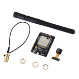


gipsyblues This dialogue box does not allow the entry of URLs.For the datasheet, please go to the website of espressif and search for esp32_datasheet_en.pdf under documentation
2020-06-06 09:28:13 полезный (1)